Aucun produit
À définir
Livraison
0,00 €
Total
Les prix sont HT
NOS SERVICES
LA SOCIÉTÉ
INFORMATION
| AFFICHEURS | CONVERSION D'ENERGIE |
|
|||||
| COMPOSANTS PASSIFS | OPTO-ELECTRONIQUE | ||||||
|
|||||||
| MODULES CONNECTORISES RF | INSTRUMENTATION RF |
|
|||||
| INTERCONNEXION RF ET OPTIQUE | COMPOSANTS ET CIRCUITS INTÉGRÉS RF | ||||||
|
|||||||
| INSTRUMENTATION GENERALE | MESURE RF ET HYPERFREQUENCE |
|
|||||||
| OPTIQUE ET TELECOMS | AUDIO & ACOUSTIQUE | ||||||||
|
|||||||||
| LOGICIELS | MATÉRIELS | SERVICES |
|
|||||||
|
| NOTRE ACCOMPAGNEMENT ET NOTRE EXPERTISE | NOS VALEURS AJOUTEES |
NOS SOLUTIONS ET REALISATIONS |
|
|||||||
|
|
| ENVIRONNEMENT | LABORATOIRE |
|
|||||
| PROCESS & CONTRÔLE INDUSTRIEL | APPLICATIONS UV & SOLAIRE | ||||||
|
|||||||
| Aérospatiale / Défense | Automobile | Contrôle / Maintenance | Education / Recherche |
 |
 |
 |
 |
| Electronique Grand Public | Environnement | Energie | Industries |
 |
 |
 |
 |
| Transport | Laboratoire / R&D | Médical | Réseau & Télécom |
 |
 |
 |
 |
 Agrandir l'image


LIVRAISON
Attention : dernières pièces disponibles !

Nous vous contacterons pour valider votre commande quand le produit sera disponible.
Date de disponibilité :
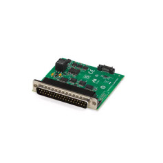
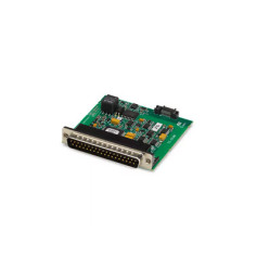
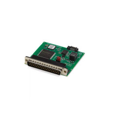
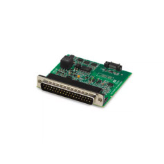
Le module d'alimentation TestScale est équipé d'une alimentation programmable capable de fournir une gamme complète de courants et de tensions, ainsi que d'une fonction de lecture à distance à boucle fermée et de protections contre les surtensions, les surintensités et les surtempératures. Ce module est compatible avec les distributions Linux courantes et peut être intégré aux logiciels NI tels que TestStand, LabVIEW et SystemLink. De plus, il est livré avec le driver NI-DAQmx, qui comprend un exemple de code et prend en charge les langages courants comme Python, C/C++, .NET et LabVIEW.
The TS-15200 is a single-quadrant power supply with one output channel.
|
|||||||
|
|||||||
|
Output power |
18 W |
||||||
The following figure illustrates the voltage and the current source capabilities of the TS-15200.
Figure 1. TS-15200 Quadrant Diagram

| Measurement Conditions | Gain Error | Offset Error | Accuracy at Full Scale[1] | |
|---|---|---|---|---|
| 2-year Calibration Interval |
Typical |
±0.06% | ±1.7 mV | ±22.1 mV |
|
Maximum |
±0.20% | ±3.1 mV | ±31.9 mV | |
| 10-year Calibration Interval |
Typical |
±0.08% | ±1.8 mV | ±23.4 mV |
|
Maximum |
±0.26% | ±3.5 mV | ±35.9 mV | |
| Measurement Conditions | Gain Error | Offset Error | Accuracy at Full Scale | |
|---|---|---|---|---|
| 2-year Calibration Interval |
Typical |
±0.04% | ±0.6 mV | ±3.0 mV |
|
Maximum |
±0.18% | ±2.5 mV | ±13.3 mV | |
| 10-year Calibration Interval |
Typical |
±0.07% | ±0.7 mV | ±4.9 mV |
|
Maximum |
±0.24% | ±2.9 mV | ±17.3 mV | |
| Measurement Conditions | Gain Error | Offset Error | Accuracy at Full Scale | |
|---|---|---|---|---|
| 2-year Calibration Interval |
Typical |
±0.09% | ±2.0 mA | ±4.7 mA |
|
Maximum |
±0.39% | ±6.2 mA | ±17.9 mA | |
| 10-year Calibration Interval |
Typical |
±0.13% | ±2.9 mA | ±6.8 mA |
|
Maximum |
±0.45% | ±8.2 mA | ±21.7 mA | |
| Measurement Conditions | Gain Error | Offset Error | Accuracy at Full Scale | |
|---|---|---|---|---|
| 2-year Calibration Interval |
Typical |
±0.09% | ±1.8 mA | ±4.5 mA |
|
Maximum |
±0.38% | ±6.1 mA | ±17.5 mA | |
| 10-year Calibration Interval |
Typical |
±0.12% | ±2.7 mA | ±6.3 mA |
|
Maximum |
±0.44% | ±8.1 mA | ±21.3 mA | |
| Specification | Gain Drift | Offset Drift |
|---|---|---|
| Voltage Programming & Measurement | ±7 ppm/°C | ±30 µV/°C |
| Current Programming & Measurement | ±45 ppm/°C | ±30 µA/°C |
| Voltage programming | 1.6 mV |
| Voltage measurement | 400 µV |
| Current programming | 900 µA |
| Current measurement | 210 µA |
|
|||||||
|
|||||||
|
|||||||
|
|||||||
|
|||||||
|
|||||||
|
Maximum total output lead drop |
Up to 1 V |
|
Maximum total output lead resistance |
Up to 1 Ω |
|
|||||||||||||||||
|
|||||||||||||||||
Notice : A minimum of 10 µF capacitive load is recommended for output stability purpose.
Refer to each cable type below for the total lead resistance and inductance (across total output leads with 10 pins on each lead).
|
|||||||
|
|||||||
|
|||||||
|
|||||||
|
|||||||
|
Maximum measurement rate |
10 kS/s |
|
Voltage input range |
11 V to 28 V |
|
Sources[8] |
Front IO connector or backplane power connector |
|
|||||||||||||
|
|||||||||||||
|
Isolation |
None |
||||||||||||
Notice : Do not insert more than two power supply modules into single backplane with maximum power output to avoid excess temperatures that automatically disable output.
|
Power consumption from backplane Vsup |
0.9 W, maximum |
|
Power consumption from Vaux[11] |
29.0 W, maximum |
|
Thermal dissipation |
11.9 W, maximum |
|
Weight |
53.3 g (1.88 oz) |
|
|||||||||
|
|||||||||
|
Pollution Degree |
2 |
||||||||
|
Maximum altitude |
2,000 m |
||||||||
|
|||||||||