Aucun produit
À définir
Livraison
0,00 €
Total
Les prix sont HT
NOS SERVICES
LA SOCIÉTÉ
INFORMATION
| AFFICHEURS | CONVERSION D'ENERGIE |
|
|||||
| COMPOSANTS PASSIFS | OPTO-ELECTRONIQUE | ||||||
|
|||||||
| MODULES CONNECTORISES RF | INSTRUMENTATION RF |
|
|||||
| INTERCONNEXION RF ET OPTIQUE | COMPOSANTS ET CIRCUITS INTÉGRÉS RF | ||||||
|
|||||||
| INSTRUMENTATION GENERALE | MESURE RF ET HYPERFREQUENCE |
|
|||||||
| OPTIQUE ET TELECOMS | AUDIO & ACOUSTIQUE | ||||||||
|
|||||||||
| LOGICIELS | MATÉRIELS | SERVICES |
|
|||||||
|
| NOTRE ACCOMPAGNEMENT ET NOTRE EXPERTISE | NOS VALEURS AJOUTEES |
NOS SOLUTIONS ET REALISATIONS |
|
|||||||
|
|
| ENVIRONNEMENT | LABORATOIRE |
|
|||||
| PROCESS & CONTRÔLE INDUSTRIEL | APPLICATIONS UV & SOLAIRE | ||||||
|
|||||||
| Aérospatiale / Défense | Automobile | Contrôle / Maintenance | Education / Recherche |
 |
 |
 |
 |
| Electronique Grand Public | Environnement | Energie | Industries |
 |
 |
 |
 |
| Transport | Laboratoire / R&D | Médical | Réseau & Télécom |
 |
 |
 |
 |

LIVRAISON
Attention : dernières pièces disponibles !

Nous vous contacterons pour valider votre commande quand le produit sera disponible.
Date de disponibilité :
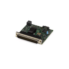
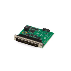
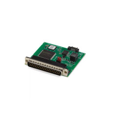
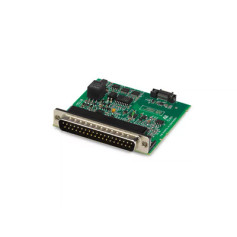
Le module d'entrée analogique TestScale vous permet de mesurer des signaux de tension d'entrée asymétriques ou différentiels avec des plages d'entrée programmables, tout en offrant une protection Ch-COM de ±30 V. Ce produit est compatible avec les distributions Linux courantes et peut être intégré avec des logiciels NI tels que TestStand, LabVIEW et SystemLink. Le driver NI-DAQmx est également inclus dans le module, avec un exemple de code et un support pour les langages courants tels que Python, C/C++, .NET et LabVIEW.
Les spécifications sont typiques dans les conditions suivantes, sauf indication contraire :
|
Number of channels |
16 differential/32 single-ended channels |
||||||
|
ADC resolution |
16 bits |
||||||
|
DNL |
No missing codes guaranteed |
||||||
|
Conversion time (maximum sampling rate) |
4 µs (250 kS/s) |
||||||
|
Input coupling |
DC |
||||||
|
Nominal input ranges |
±10 V, ±5 V, ±1 V, ±0.2 V |
||||||
|
Minimum overrange, ±10 V range |
4% |
||||||
|
Maximum working voltage for analog inputs (signal + common mode) |
Each channel must remain within ±10.4 V of COM |
||||||
|
|||||||
|
Input bias current |
±100 pA |
||||||
|
|||||||
|
Analog bandwidth |
350 kHz |
||||||
|
|||||||
Notice : Exceeding overvoltage specifications may result in data corruption on non-overvoltaged channels.
|
|||||||||||
|
|||||||||||
|
|||||||||||
|
CMRR, DC to 60 Hz |
100 dB |
||||||||||
Figure 1. CMRR, AI <0..31>

The following values are based on calibrated scaling coefficients, which are stored in the onboard EEPROM.
The following statements apply to the accuracy specifications across all voltage ranges:

where
| Measurement Conditions | Gain Error | Offset Error | Accuracy at Full Scale | ||
|---|---|---|---|---|---|
| 2-Year Calibration Interval | With Self Calibration |
Typical (23 °C ± 5 °C) |
±0.017% | ±3.1 mV | ±5.6 mV |
|
Maximum (0 °C to 55 °C) |
±0.070% | ±11.3 mV | ±19.1 mV | ||
| Without Self Calibration |
Typical (23 °C ± 5 °C) |
±0.020% | ±6.1 mV | ±8.9 mV | |
|
Maximum (0 °C to 55 °C) |
±0.100% | ±38.1 mV | ±48.9 mV | ||
| 10-Year Calibration Interval | With Self Calibration |
Typical (23 °C ± 5 °C) |
±0.027% | ±4.1 mV | ±7.6 mV |
|
Maximum (0 °C to 55 °C) |
±0.101% | ±14.4 mV | ±25.3 mV | ||
| Without Self Calibration |
Typical (23 °C ± 5 °C) |
±0.031% | ±7.1 mV | ±11.0 mV | |
|
Maximum (0 °C to 55 °C) |
±0.131% | ±41.2 mV | ±55.1 mV |
| Measurement Conditions | Gain Error | Offset Error | Accuracy at Full Scale | ||
|---|---|---|---|---|---|
| 2-Year Calibration Interval | With Self Calibration |
Typical (23 °C ± 5 °C) |
±0.019% | ±1.6 mV | ±3.0 mV |
|
Maximum (0 °C to 55 °C) |
±0.072% | ±5.8 mV | ±9.8 mV | ||
| Without Self Calibration |
Typical (23 °C ± 5 °C) |
±0.022% | ±3.1 mV | ±4.6 mV | |
|
Maximum (0 °C to 55 °C) |
±0.102% | ±19.9 mV | ±25.4 mV | ||
| 10-Year Calibration Interval | With Self Calibration |
Typical (23 °C ± 5 °C) |
±0.029% | ±2.1 mV | ±4.0 mV |
|
Maximum (0 °C to 55 °C) |
±0.103% | ±7.2 mV | ±12.8 mV | ||
| Without Self Calibration |
Typical (23 °C ± 5 °C) |
±0.033% | ±3.7 mV | ±5.8 mV | |
|
Maximum (0 °C to 55 °C) |
±0.133% | ±21.5 mV | ±28.6 mV |
| Measurement Conditions | Gain Error | Offset Error | Accuracy at Full Scale | ||
|---|---|---|---|---|---|
| 2-Year Calibration Interval | With Self Calibration |
Typical (23 °C ± 5 °C) |
±0.021% | ±0.4 mV | ±0.7 mV |
|
Maximum (0 °C to 55 °C) |
±0.074% | ±1.4 mV | ±2.3 mV | ||
| Without Self Calibration |
Typical (23 °C ± 5 °C) |
±0.024% | ±0.8 mV | ±1.2 mV | |
|
Maximum (0 °C to 55 °C) |
±0.104% | ±5.3 mV | ±6.5 mV | ||
| 10-Year Calibration Interval | With Self Calibration |
Typical (23 °C ± 5 °C) |
±0.031% | ±0.5 mV | ±0.9 mV |
|
Maximum (0 °C to 55 °C) |
±0.105% | ±1.5 mV | ±2.7 mV | ||
| Without Self Calibration |
Typical (23 °C ± 5 °C) |
±0.035% | ±0.9 mV | ±1.4 mV | |
|
Maximum (0 °C to 55 °C) |
±0.135% | ±5.6 mV | ±7.1 mV |
| Measurement Conditions | Gain Error | Offset Error | Accuracy at Full Scale | ||
|---|---|---|---|---|---|
| 2-Year Calibration Interval | With Self Calibration |
Typical (23 °C ± 5 °C) |
±0.027% | ±0.2 mV | ±0.3 mV |
|
Maximum (0 °C to 55 °C) |
±0.080% | ±0.5 mV | ±0.7 mV | ||
| Without Self Calibration |
Typical (23 °C ± 5 °C) |
±0.030% | ±0.3 mV | ±0.4 mV | |
|
Maximum (0 °C to 55 °C) |
±0.110% | ±2.4 mV | ±2.7 mV | ||
| 10-Year Calibration Interval | With Self Calibration |
Typical (23 °C ± 5 °C) |
±0.037% | ±0.2 mV | ±0.3 mV |
|
Maximum (0 °C to 55 °C) |
±0.111% | ±0.6 mV | ±0.9 mV | ||
| Without Self Calibration |
Typical (23 °C ± 5 °C) |
±0.041% | ±0.3 mV | ±0.4 mV | |
|
Maximum (0 °C to 55 °C) |
±0.141% | ±2.5 mV | ±2.8 mV |
| Range | Gain Drift | Offset Drift | Noise, σ*,† |
|---|---|---|---|
| ±10 V | ±5 ppm/°C | ±470 µV/°C | 260 µV RMS |
| ±5 V | ±250 µV/°C | 130 µV RMS | |
| ±1 V | ±70 µV/°C | 30 µV RMS | |
| ±0.2 V | ±30 µV/°C | 20 µV RMS | |
|
* Differential terminal configuration only. NI recommends using differential signal configuration for improved noise performance. Refer to the TS-15100 feature documentation on ni.com/docs for information on terminal configuration. † For optimum noise performance, do not install the TS-15100 in a slot adjacent to the TS-15200 (Programmable Power Supply module). |
|||
|
INL |
±75 ppm of range |
|
Reference drift (all input ranges) |
±5 ppm/°C |
|
Overvoltage protection |
±30 V |
||||||||||||||||||
|
|||||||||||||||||||
|
Source |
PFI 0 |
||||||||||||||||||
|
Delay |
100 ns maximum |
||||||||||||||||||
|
Power consumption from backplane, Vsup |
650 mW maximum |
|
Thermal dissipation |
800 mW maximum |
|
Weight |
39.7 g (1.40 oz) |
|
|||||||||
|
|||||||||
|
Pollution Degree |
2 |
||||||||
|
Maximum altitude |
2,000 m |
||||||||
|
|||||||||
(°-°t)